
Summary
Keywords
Full Transcript
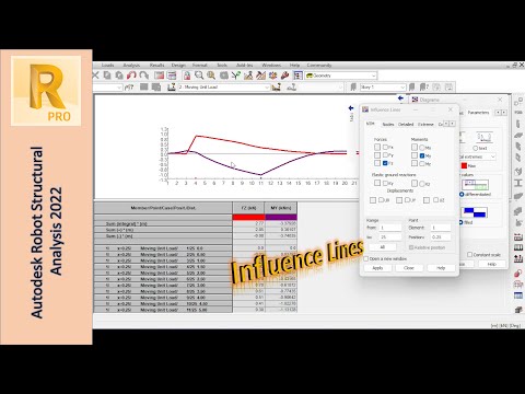
In this video, we'll explore the concept of influence lines and how to use them in Autodesk Robot. We'll cover the basics of influence lines, including what they are, how they're used, and why they're important in structural engineering. We'll start by discussing the theory behind influence lines, including how they're used to determine the maximum effect of a load on a structure. We'll also cover how to create influence lines in Autodesk Robot, including how to define your structure and apply loads. Next, we'll dive into some practical examples of how to use influence lines in Autodesk Robot. We'll cover topics such as determining the maximum bending moment and maximum shear force. Throughout the video, we'll provide step-by-step instructions and helpful tips to guide you through the process of creating and using influence lines in Autodesk Robot. Whether you're a beginner or an experienced user, this video will provide you with valuable insights into the theory and practice of influence lines in structural engineering. Current Video Ideas for the Future: - More details about modal participation / report? - Masses and stiffnesses to control modes - LL Reduction in ACI/ASCE (vertical and horizontal) - A possible way to model columns with pressure areas - Deeper dive into slab reinforcement. - Raft with larger thickness and positions - Robot - seemingly - erratic deformation when supported by beams and columns - A way to manually “clean-up” simple mesh like the above - Wood and Armer Moments in Slabs and their meaning - Complex and Principle results - Simple TBM tunnel lining analysis in robot Timestamps: 0:00 Introduction 0:51 What are Influence Lines? 8:00 Influence Lines in Autodesk Robot 15:35 Results Discussions 19:10 Outro

Continue this lesson in the app
Install CourseHive on Android or iOS to keep learning while you move.